Load balancing Change Healthcare Radiology
Updated on February 3, 2026
•
Published on April 2, 2025
Benefits of load balancing Change Healthcare Radiology
The top three benefits of load balancing Change Healthcare Radiology are the following:
- High Availability (HA): Load balancing is crucial for ensuring the continuous availability of mission-critical imaging systems. By distributing DICOM (Digital Imaging and Communications in Medicine) studies and system traffic across multiple servers, a load balancer ensures that if one server fails or needs maintenance, traffic is automatically and seamlessly rerouted to the remaining healthy servers. This redundancy is vital in a 24/7 patient care environment. Any downtime in image access can directly delay diagnosis and treatment, especially for urgent or emergency cases. Load balancing helps achieve near zero downtime. It also allows IT teams to perform necessary server maintenance, upgrades, or patches on individual servers without disrupting the workflow for radiologists and clinicians.
- Enhanced performance: Load balancing prevents system bottlenecks and maximizes the speed of image processing and retrieval, which are critical in high-volume radiology departments. The load balancer intelligently directs incoming imaging requests (e.g., studies from a CT or MRI scanner, or image retrieval requests from a viewing workstation) to the server that is least busy or has the most available resources. This prevents any single server from becoming overwhelmed, ensuring that large-file images (like those from 3D mammography or advanced CT protocols) are processed and delivered rapidly to the radiologist’s workstation. Faster processing directly leads to improved turnaround times (TATs) for reports.During periods of high demand (e.g., peak emergency department hours), the system can scale dynamically to handle sudden spikes in data volume without suffering performance degradation.
- Improved radiology workflows: While often focused on the technical aspects of the network, load balancing also has a direct, positive impact on the human side of the radiology workflow. Specialized radiology workload management systems, often utilizing the principles of load balancing, can automatically and equitably distribute cases among the available radiologists. This distribution can be based on factors like case urgency/priority, radiologist subspecialty/skillset, and current individual workload (to prevent burnout). By minimizing the time radiologists spend manually selecting cases from a lengthy, undifferentiated worklist, and by ensuring they have immediate, uninterrupted access to the images, the system helps them focus on their core task: diagnosis and reporting. Fair and automatic distribution helps reduce stress among radiologists and prevents the less urgent, less desirable, or more complex cases from being consistently overlooked or cherry-picked by others.
About Change Healthcare Radiology
Change Healthcare Radiology is an integrated, web-based PACS system for radiologists who want to keep costs down without compromising features or capabilities. It delivers a comprehensive enterprise radiology PACs in a number of different ways:
- Integrated diagnostic imaging and radiology workflow management solutions with VNA and EHR interoperability to help reduce clinical variation.
- Immediate access to each patient’s imaging records and medical history, improving patient care and clinician engagement.
- Cost-effective solutions that meet the requirements of different sites and end users.
- Integrated, advanced image analysis capabilities directly within the radiologist’s readflow.
- Integrated clinical, communication, and workflow tools to increase radiology’s participation throughout the care cycle.
- High-quality image display, workflow efficiency, and system integration capabilities to enhance performance.
It is highly recommended that you have a working Change Healthcare Radiology environment first before implementing the load balancer. Configuration changes within the Change Healthcare Cardiology platform itself may also be required before load balancing can then be enabled.
Why Loadbalancer.org for Change Healthcare Radiology?
Our deployment recommendations aren’t theoretical; they have been field tested and rigorously validated by Change Healthcare experts. This means you can be completely confident that the solution described is robust, reliable, and backed by the real-world operational experience of a global leader in healthcare technology.
Contact our Sales team for full details of how to deploy and configure the Loadbalancer.org appliance for Change Healthcare Radiology and more information on our partnership.
Endorsed by Dirk De keersmaecker, Principal Product Manager, Change Healthcare
“If you want to know how to impress your customers, contact Loadbalancer.org and ask how they do it”.
Loadbalancer’s intuitive Enterprise Application Delivery Controller (ADC) is also designed to save time and money with a clever, not complex, WebUI.
Easily configure, deploy, manage, and maintain our Enterprise load balancer, reducing complexity and the risk of human error. For a difference you can see in just minutes.
And with WAF and GSLB included straight out-of-the-box, there’s no hidden costs, so the prices you see on our website are fully transparent.
More on what’s possible with Loadbalancer.org.
How to load balance Change Healthcare Radiology
For Change Healthcare Radiology, Layer 4 NAT mode and Layer 7 Reverse Proxy mode are recommended.
About Layer 4 NAT mode load balancing
Layer 4 NAT mode is a high performance solution, although not as fast as layer 4 DR mode. This is because real server responses must flow back to the client via the load balancer rather than directly as with DR mode.
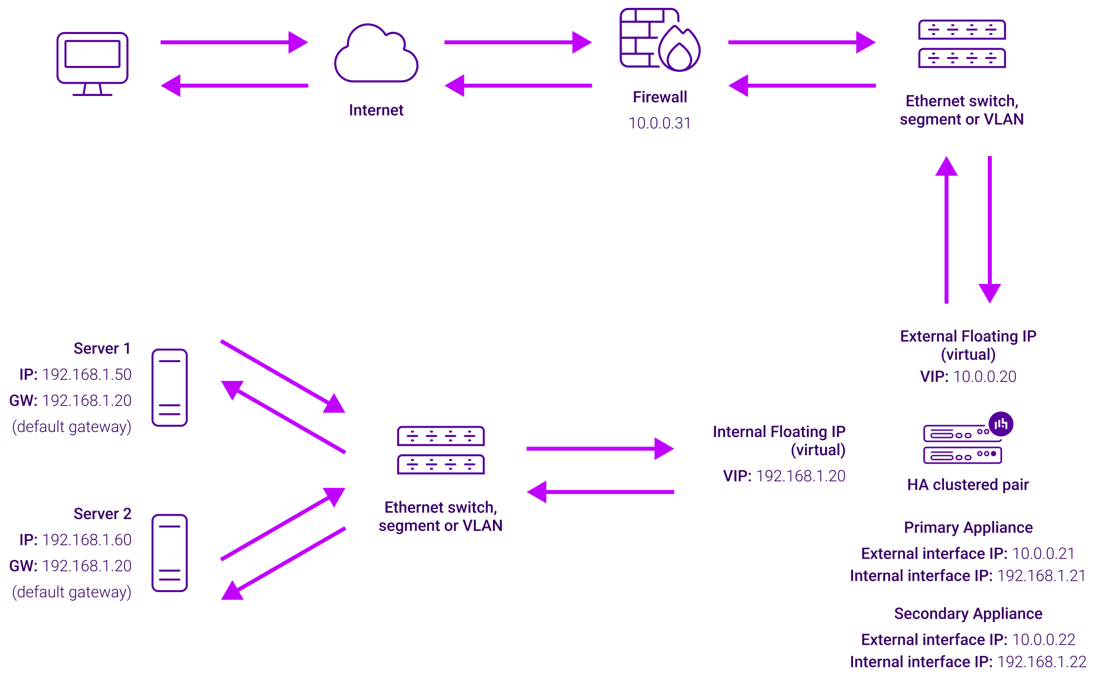
The load balancer translates all requests from the Virtual Service to the Real Servers. A Two-arm configuration is used where the load balancer has 2 network interfaces, one in each subnet. The VIP is brought up in one subnet and the load balanced Real Servers are located in the other.
Normally eth0 is used for the internal network and eth1 is used for the external network although this is optional. Any interface can be used for any purpose. If the Real Servers require Internet access, Autonat should be enabled using the WebUI menu option: Cluster Configuration > Layer 4 – Advanced Configuration, the external interface should be selected. The default gateway on the Real Servers must be set to be an IP address on the load balancer.
Clients can be located in the same subnet as the VIP or any remote subnet provided they can route to the VIP. If you want Real Servers to be accessible on their own IP address for non-load balanced services, e.g. RDP, you will need to setup individual SNAT and DNAT firewall script rules for each Real Server or add additional VIPs for this.
Port translation is possible with Layer 4 NAT mode, e.g. VIP:80 → RIP:8080 is supported. NAT mode is transparent, i.e. the Real Servers will see the source IP address of the client.
About Layer 7 Reverse Proxy load balancing
Layer 7 Reverse Proxy uses a proxy (HAProxy) at the application layer. Inbound requests are terminated on the load balancer and HAProxy generates a new corresponding request to the chosen Real Server. As a result, Layer 7 is typically not as fast as the Layer 4 methods.
Layer 7 is typically chosen when enhanced options such as SSL termination, cookie based persistence, URL rewriting, header insertion/deletion etc. are required, or when the network topology prohibits the use of the Layer 4 methods.

Because Layer 7 Reverse Proxy is a full proxy, any server in the cluster can be on any accessible subnet, including across the Internet or WAN.
Layer 7 Reverse Proxy is not transparent by default i.e. the Real Servers will not see the source IP address of the client, they will see the load balancer’s own IP address by default, or any other local appliance IP address if preferred (e.g. the VIP address). This can be configured per Layer 7 VIP.
If required, the load balancer can be configured to provide the actual client IP address to the Real Servers in two ways:
- Either by inserting a header that contains the client’s source IP address, or
- By modifying the Source Address field of the IP packets and replacing the IP address of the load balancer with the IP address of the client.
Layer 7 Reverse Proxy mode can be deployed using either a one-arm or two-arm configuration. For two-arm deployments, eth0 is normally used for the internal network and eth1 is used for the external network, although this is not mandatory.
No mode-specific configuration changes to the load balanced Real Servers are required.
Port translation is possible with Layer 7 Reverse Proxy e.g. VIP:80 → RIP:8080 is supported. You should not use the same RIP:PORT combination for Layer 7 Reverse Proxy VIPs and Layer 4 SNAT mode VIPs because the required firewall rules conflict.